Required Background Knowledge
Before we can start testing, we must first understand how to construct a sensor and the underlying physics of what they are measuring.
Fluid Dynamics Background -
We will be using the same type of probe as the commercially available aero sensors, called a kiel probe, to measure the wind speed. From there we can perform some calculations to estimate our CdA (coefficient of drag*area), where we want our CdA to be as low as is sustainable, not necessarily as low as possible. We will expand on this idea later during the testing phase.
A Kiel probe is simple a device that measures stagnant vs dynamic pressure. In plain English, air flows down the central tube and creates an area of relative high pressure, but the holes on the sides experience no change in pressure compared to the no flow condition (1). By connecting a differential pressure sensor to the ports of our probe, we can using Bernoulli’s equation to get the velocity of the air.
(1) This is not true under real test conditions, as there is some pressure fluctuation that we will handle later on
From NASA, Pitot Tube Operation
For the keen eyed among you, you’ll notice that the above graphic calls out a “pitot tube,” not a kiel probe. A kiel probe is essentially a pitot tube with a shroud around it to smooth the airflow. As we mentioned above, pitot tubes work by having open ports on the sides to measure static pressure, so any lateral flow will affect our static pressure reading and throw off our air speed calculation. The shroud ensures that air can only flow parallel to the pitot tube, so yaw angle matters much less. In aerospace or motor sport applications where yaw angle is far more important for stability and safety, they will often use very complicated pitot tube/yaw probe setups to gather that data, but it is not as applicable for our purposes and adds a tremendous amount of complexity.
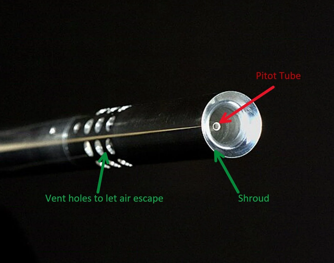
Kiel Probe components
Instrumentation/Data Processing Hardware Background -
Since balancing cost and ease of use was a significant factor in this design, I opted to use the Arduino MKR platform since it’s relatively cheap (though there are cheaper options out there which sacrifice flexibility and ease of use) and can be easily combined with sensor shields to obtain several very useful measurements, such as temperature and humidity, without the need for separate sensors. We can use 0-5 analog, digital, or I2C sensors with this arduino, so there is a wide arrays of options should you choose to deviate from my design. For the differential pressure (dP) sensor, I chose one from amazon that uses the I2C communication protocol since these can have their data output onto a single communications bus. This simplifies the wiring considerably and lets us save on space, which will be very important for the mechanical design.
Programming Background -
Because I chose the arduino platform, we can program our system entirely using the arduino IDE. We can quite easily download all the libraries we need directly through the IDE as well, so setup for this is extremely easy. Additionally, the documentation for the Arduino IDE (https://docs.arduino.cc/) is extremely helpful and easy to navigate.
The Libraries we will need are:
Arduino_MKRENV
SPI
SD
ArduinoBLE (Optional for garmin integration)
WiFiNINA (Optional for additional connectivity)
Later on, I will develop an application for garmin that allows this data to be fed directly to the headunit, but for now all analysis is done in post-processing on an external device.